Thursday, June 30, 2016

Throttle Position Sensor (TPS) Pin Layout & Removal

The protective heat shrink tubing on the wires for the TPS and AFM harness on my car were not in good shape, the tubing had become hard and brittle and was starting to look pretty sad. Surprisingly, the wires under the tubing were in good shape. So, I needed to remove the TPS connector so I could slip new protective tubing over the wires.
 
The TPS sensor is a AMP junior timer series connector. To remove the pins from the connector insert a 1.2mm screwdriver or 2 prong remover tool (Lisle Toolin the front of the connector in the small square at the bottom. Once it is fully seated you might hear a small click/clunk which is the metal tab at the bottom of the pin being pushed up. Remove the tool and insert the screwdriver in the middle area of the pin and push it out of back.
 
Below is a layout diagram of the TPS connector which should assist during reassembly.
 
 
1 - White/Black
2 - Empty
3- Brown
4 - White/Green
5 - White/Blue
6 - White/Red
 
Final Result
 

Tuesday, June 28, 2016

Headgasket Thickness & Compression Ratio

Determining what thickness of head gasket to use on a modified 951 motor was a bit of a trip down a rabbit hole. The information scattered about the internet had a wide variation of opinions on what to actually use. I eventually had a lengthy discussion with a well respected engine builder about exactly what thickness to choose and why to choose it.
 
But first a little background as to why I thought I might have needed a thicker gasket in the first place. The cylinder head that is to be used for this project was originally a Lindsey Racing Stage 2 with LR springs and moly retainers. In addition it was o-ringed for the stock 100mm bore size. The problem was Cometic MLS head gaskets should not be run with a o-ringed cylinder head.
 
This is a quote directly from the Cometic website in the technical support section:
 
Can MLS head gaskets be used with motors setup with o-rings or receiver grooves around the cylinder bores?
 
No. MLS head gaskets require smooth, flat and true head and deck surfaces to seal. Most of the time with o-ring setups the wire and groove fall where our gasket’s combustion seal is located; therefore, the wire will hold the gasket and not allow proper compression while the receiver grooves allow combustion gases to escape."
 
So the first problem to solve was machining the old cylinder head down to a flat surface below the o-ring grooves so that the new gasket will seat properly. This required the removal of .03" of material, leaving the cylinder head at 22.83mm as measured from the factory "L shaped" measuring point A. For reference a stock cylinder head is 24mm +/- .1mm
 
 
This reduction in cylinder head height had me concerned about the overall impact on the engine compression ratio and engine timing.
 
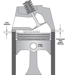
However, it turns out that in reality the real critical dimension for these engines is actually the piston to deck clearance. As the name suggests its the measurement of the piston at TDC vs the height of the deck. Negative numbers mean the piston is below the deck, positive above.
 
There are a bunch of different ways to obtain this measurement but this is how I did it. I brought the cylinder piston to TDC with dial gauge and bridge via sweep method, taking the measure along the center line. Zeroed the dial for the TDC level. Then I moved the dial gauge over to the deck, over the centerline and recorded the difference. I took a measure at both the piston front and rear.
 
As long as the you have zero to negative piston to deck clearance you can and should use a stock thickness (.0433") gasket to maintain the ideal quench/squish. A good write up about quench can be seen here. In short .04" is the magic number If the compression ratio is increased as a result of keeping near it, most likely it can be handled in a better way with engine management. For my particular build since I'm already outside the scope of the stock management with the increased bore size  the standalone system will easily be able to accommodate the adjustment.
 
 
His advice was confirmed in Turbocharging Performance Handbook by Jeff Hartman that I had on the shelf. On page 86 he discusses installing thicker head gaskets and the squish effect very briefly saying:
 
"Worst of all, it could degrade the "squish" effect in the combustion chambers, which can actually be a greater pro-knock factor than a little more compression.... It is critical that a compression lowering strategy not mess with the squish ring."
 
When you have positive values (ie: the piston is actually protruding above the deck at TDC) then you will need to go to a thicker gasket by adding the clearance number to .0433" to get the ideal size.
 
Using the Summit Compression Calculator I was able to find the new compression ratio with the following information of the build.
 
Bore: 104mm
Stroke: 78.9mm
Cylinder Head Volume: 48.5cc
Effective Dome Volume: 33.4cc
Deck Clearance: -.009in
Compressed Gasket Thickness: .045"
# of Cylinders: 4
 
Results in a 8.47:1 Static Compression Ratio.
 
Hopefully this helps clear up some of the misinformation floating around the internet.
 

Sunday, June 26, 2016

Piston Volume Measurement

Knowing the volume (dish/dome) of the piston is an important factor in the engine compression calculation. In general the manufacturer provides the volume spec but what if you have a piston of unknown spec? In that case you'll need the measure its volume with a fluid and do some math.
 
First thing I did was get out a dial gauge and a dial gauge bridge. I zeroed the dial gauge of the deck surface where the Plexiglas cover for the volume measurement will rest. I also rubbed a light layer of oil near the upper bore to help assist the piston ring seal (since we will later be filling this area with liquid).
 
 
Next I positioned the dial gauge over the piston edge and rotated the crankshaft until the desired piston was near the dial gauge probe. Since I wanted the piston to be set .1inch below the zeroed deck (2 rotations of the dial gauge). (Side note: I like to use a rubber strap wrench on the crank drive gear as this make rotating the engine super easy and causes no damage). 
 
 
Now that cylinder 1 is at a known depth I prepared the other necessary items. These included Jeg's economy cc kit, Vaseline, rubbing alcohol (Water would be fine also) and food coloring. Food color your liquid for added visibility.


Fill the syringe with 60cc of liquid, purging any air bubbles. Apply Vaseline to the deck surface where the Plexiglas plate will sit to create a seal. Then dispense into the plate hole until the entire area is filled. This may require you to reposition the fill hole over any trapped air bubbles to get an accurate measure. You can suck out the liquid with the syringe to reuse it and make cleanup a bit easier.
 
 
Record the volume remaining in the syringe for the cylinder and repeat for remaining pistons. Subtract the remainder from 60cc to get the volume.
 
My measurements came out in the 55 to 56cc range. I used 55cc for the next calculations.
 
To determine the volume of the unknown space we need to subtract away the volume of the cylinder above it. This was why we needed to know the depth earlier so we know the cylinder height. The bore of this motor is 104mm, which is the cylinder diameter.
 
h = .1in = 2.54mm
r = 104mm/2 = 52mm
 
Volume of a cylinder = PI * r^2 * h
V = PI * 52mm^2 * 2.54mm
V = 21,576mm^3 * (1cm^3/1000mm^3)
V = 21.58cm^3 (cc)
 
Now we can subtract out the extra volume from our measured volume.
 
55cc - 21.58cc = 33.42cc
 
33.4cc is the piston (dish) volume.
 
Additional Note: Make sure you do a good job of soaking up all the remaining liquid in the chamber, then recoat the cylinder bore with a light film of oil. Turn the engine over a few times to be sure you got it all. 

Friday, June 24, 2016

Clutch Fork Bearing Removal/Installation

Removing and installing the bearings in the clutch fork can be a bit of a tricky task. Some people have reported that you can hammer them out with a bolt just about the same size as the bearing. I tried this with a few blows of a 3lb dead blow hammer but it did not seem to be the best way to go about doing it. Additionally, I tried a C-clamp but I wasn't able to apply enough leverage to the handle to get them moving.
 
A bench vise is a better solution but unfortunately the jaws on mine were not wide enough to fit the fork and a 5/8" socket to press in. I needed something thinner but still the same diameter.
 
The solution was to use nickels which you can gradually stack up and tape in place until you get the bearing pressed out about half way. Then I was able to use the 5/8" socket to finish the job. You can use a piece of masking tape to help keep the stack lined up and in place.
 
 
To install the new bearings place a nickel over the bearing face to protect it from the vice and slowly press in. I had difficulty getting them lined up exactly square so I placed the bearings in the freezer for a few hours, problem solved.
Press bearings from inside to outside of fork in direction of arrow 

Once halfway then was able to finish with the 5/8" socket