Sunday, January 28, 2018

Intense Wheel Restoration (Ammo NYC method)

Not long ago, I picked up a set of BBS Carrera 3 wheels for a really nice price on the second hand market. As with the majority of used wheels they had there share of imperfections this included some mild curb rash, black buildup (brake dust, dirt, asphalt) on most of the rim interior and scratches from improper cleaning maintenance on the front faces. I figured I would try my best to bring them back to life and if I was still unhappy I would consider sending them out for professional repair and repaint.

I mainly followed Larry's procedure from Ammo NYC on how to go about cleaning them. Larrys video here. The only major difference for my method was that since I do not own a RA polisher I had to do all the compounding by hand. I took some photos along the way to document how it came out.

Cleaning Materials (Wheel Cleaner, Dish Soap, Spray Wax, 105 Compound, Ultimate Compound, Sponge, Soft Brush, Clay, Microfiber Towels)
In addition to the cleaning materials pictured above I also used a respirator (during compounding), nitrile gloves, old towels and a large plastic storage bucket.

Pictured below is the initial condition of the rim, I don't think the camera was able to pick up the fine scratches that resulted from poor cleaning technique but trust me they were there on the majority of the outer lip and between the spokes.

Initial Condition - Front

Initial Condition - Back
Since it is winter and cold here in the northeast I attempted to do everything in my bathroom. And aside from having the sit on the floor while doing the manual labor that location worked pretty well.


Wheel in dish soap bath

Resulting water after dish soap/wheel cleaner bath and sponge cleaning


Rim after dish soap bath

Rim after clay bar treatment. Some of the black stain was removed and the clay was good at removing stuck asphalt

Rim after compounding. 105 worked well by hand.

Final Result
After I was finished with the compounding I did do one additional step which was to use Klasse All-In-One to add a layer of protection back on the surface to help prevent/reduce future build up. I did not take a photo after that. Total time per wheel for all 4 steps was about 6 hours, with a large portion of that being devoted to hand compounding.

Tuesday, August 2, 2016

Turbo Auxiliary Coolant Temperature Sensor Pipe Modification

One of the accommodations needed to be made when outfitting a new turbo that does not use a KKK center section is to re-route the coolant temperature sensor for the auxiliary coolant pump. The sensor triggers the coolant pump to turn on and off after the car has been shut down to continue to flow through the turbo to reduce wear. It can cycle many times after the car is turned off to accomplish its job. Basically this functions as a OEM turbo timer.

The turbo I have replaced the K26 with is a Garrett GT3076R. The GT30 uses a 14mm x 1.5 fitting on both sides of the center section for cooling. To adapt to a more common fitting size I used a 14mm male to -10AN male. -6AN and - 10AN are the most readily available center section adapters for the GT. I choose to go with the larger -10AN to ensure maximum flow. A 1/2" copper crush washer on the 14mm side that connects to the turbo is also necessary.

To modify the sensor pipe we first need to cut off the banjo fitting/pipe that is attached to the sensor mount (I borrowed the general idea for the modification from Paulyy on Rennlist). Using a hacksaw and a bench vise to hold the pipe you can make quick work of this. Depending on the cleanliness of the cut you may choose to smooth the surface with medium grit sandpaper. Next, I drilled the hole to the necessary size for a 3/8" x 18 NPT tap. Required drill sizes are either 37/64" or 9/16". Then tap the hole with the 3/8" tap. This will allow us to a 3/8" NPT to -10AN adapter fitting. Make sure to use thread sealant on the fittings. After cutting I painted the pipe with VHT engine metallic titanium silver blue.


The layout of the adapters is as follows. On the sensor side starting with the nearest to the turbo 14mm male to -10AN male > 90* swivel -10AN female to -10AN female > -10AN male to 3/8" NPT. On the auxiliary coolant pump side 14mm male to -10AN male > -10AN female to -10AN female coupler > -10AN male to 10 push loc hose barb.
 
Due to the very tight center section of the GT series turbo and the close proximity of the hot side clocking bolts the 90* swivel adapter is going to have to some problems fully tightening down on the 14mm adapter in most scenarios. One option to replace the 2 clocking bolts with low profile bolts (similar to what is used near the oil drain). Alternatively you can file down the points on the front 1/3 of the swivel adapter to gain enough clearance to pass the bolt; I ended up choosing the later. 


Thursday, July 28, 2016

Power Steering Hard Line Cooler Hose and Clamp Discussion

One of the power steering hoses off the reservoir on my car was in pretty poor shape. Of course it is the one with the cooler hardline integrated (since I replaced the other hose already). This part is expensive if you go for a OEM replacement because it comes with the cooler hardline coil and crimped hose as one unit. To add to the frustration the hardline end is a different diameter then the reservoir.
 
Thankfully Bruce at Arnworx has taken some of the annoyance out of this job by having a nicely preassembled hose with a protective heat shield over the 90* bend area where the hose meets the bending reducer. Available here. Installation is pretty straight forward so I'm not going to cover that but instead I'm going to talk about why the old hose was in such poor shape.
 
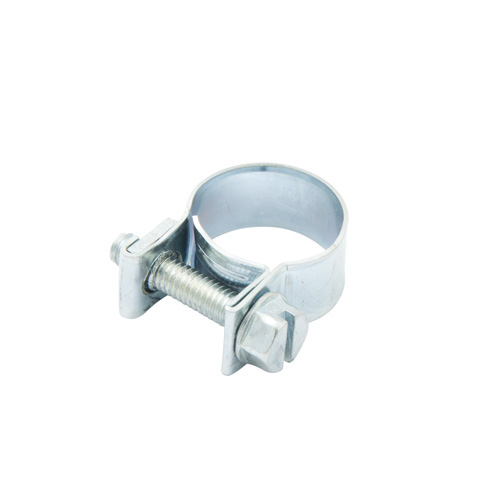
The main reason was a result of a low quality hose clamp. There are a wide variety of clamps on the market and in my experience the kind that was installed on this hose are the worst. They are the perforated worm clamp. Because of the punched out metal to make the screw track these leave large impressions on rubber hose. Silcone hose and couplers are even more susceptible to clamp damage then rubber so a quality clamp is essential when using Silcone. A better solution is either an embossed worm style clamp, fuel injector style, t-bolt or other clamp that has a solid continuous protective surface on the inside. Thankfully most of the factory clamps on the 944 are Norma brand embossed worm style so this is generally not an issue but worth thinking about if you are going to be replacing aging clamps.


Embossed Clamp
 
Worm Clamp
Fuel Injector Style Clamp
 

Friday, July 15, 2016

Fuel Tank Cover Strap Refurb

While replacing the fuel strainer at the lower part of the fuel tank I noticed that the support strap for the fuel tank lower cover was pretty rusty. In fact it looked like it spent a little too much time at the enchantment under the sea dance. I figured while I was down there I should probably refurbish the part.

Before
 
In addition to paint, the factory also installed some cushioning foam to the top of the strap where it contacts the covers and gas tank. Very similar resemblance to foam weather-stripping from home improvement stores. I was surprised to see on the Frost King packaging that it states: "Many automotive and marine uses". 
 
Step 1: Using a grinder or drill wire wheel as much rust, old paint..etc from the part as possible. I used a grinder with a 4" brass wire wheel. Ideally a media blaster is best for this type of work but I don't own one.
 
Step 2: Clean/Wash/Dry the part to prepare for painting. I cleaned it with simple green and a scrub brush, then rinsed with water. Brake cleaner is another popular choice.
 
Step 3.1: Paint the part. For this piece I am using 2 different paints. The first is a rust converting paint such as Rustoleum Rust Reformer. Even though I probably removed the majority of the rust during step 1 this goes the extra mile to be sure its not coming back. 2 light coats of Reformer about 10mins apart followed by a 24 hour drying cycle.
 
Note: If you are going to paint inside like I had to due to weather conditions make sure you have a vapor respirator mask. You can make a "booth" area out of some old cardboard and hang it from an A frame ladder, just be creative!
 
 I ended up using a bit more brown paper then pictured on the sides to catch overspray.
 
Step 3.2: Follow up with VHT Chassis satin black as the top coat. 2 light coats followed by 1 medium "wet" coat, allowing for 10mins drying between each application. The part should be ready to handle in 3 hours.
 
Step 4 (Optional): Apply Frost King adhesive weather-stripping to the section of the strap that contacts the gas tank and lower covers. If needed use 3M Super 77 for additional adhesive on weather stripping. Clamp for about an hour to assist the glue. Super 77 is pretty tacky, so you'll need rubbing alcohol for removing any extra.


Step 5: Bask in the glory of knowing no one will notice your hard work on this part hidden away under your vehicle.
 

Finished!


Monday, July 11, 2016

General Project Update

Project update as of early July 2016.
 
I'm waiting on the collar nut for the timing roller and a few other random parts. I also need to send some parts to the local plating shop to get a new yellow zinc chromate finish.
 
LR Stage 2 cylinder head after decking to remove o-ring grooves (Performed at Windsor Automotive Machine)
 
 
Cyl 1 @ TDC with the gasket on
 
If you look carefully you might be able to see the alignment marks I scribed on the balance shaft housing.
Extra help with alignment for a no cover install.


Saturday, July 9, 2016

Fuel Damper/Fuel Pressure Regulator and Jumper Hose (Fuel in Vacuum Lines)

The fuel damper and associated jumper hose have been a source of problems for these cars especially as they get older. The rubber hose is the most straight forward as it tends to get rock solid with age and eventually becomes a location for a fuel leak.
A failing fuel damper and/or fuel pressure regulator is a bit harder to identify. Symptoms consist of fuel in the vacuum line at the back of the damper/regulator which in severe cases can travel into the intake manifold or even the KLR vacuum line. Since the KLR line is clear you can actually spot the fuel traveling in the hose (See photo 2 below, the trapped gas is inside the circles). Others symptoms are hard to near impossible hot starts and fuel pressure loss over time at the rail causing long, lazy starts. In the case of the difficult hot starts this is likely due to the fact that as the gas migrates its way down the clear vacuum line and arrives at the KLR computer sensor it really confuses the system; when the gas eventually dries out near the computer things will appear to operate as normal for a brief period until the cycle repeats again.
Replacement on the bench if the rail has already been removed from the car can be a bit tricky since it can be a bit awkward to gently yet firmly clamp the rail to a work area to allow removal of the large nut securing the damper to the rail. Mine was particularly stuck and required me to use a chain whip vise grip on the damper to provide enough counter torque against a breaker bar.

Gas in KLR Vacuum Line (Image: 951North - Rennlist)

Friday, July 8, 2016

Flywheel Measurements and Pins

Switching to a aftermarket flywheel? Or perhaps you have acquired a flywheel with missing or removed "grub screws". I have taken a few measurements off the factory 87 flywheel which should assist in setting the screws to the correct height. This is important because the screw is what the factory sensor reads to determine engine position. If it is not set to the correct height you can get problems from erratic starting behavior to no starts. When setting the pins to the final height use some Loctite thread locker to ensure they stay at the desired height.
 
As a side note the stock flywheel has 3 screws, 2 on the same plane and 1 further back on a different plane. Most aftermarket wheels only have 1 screw. The stock Motronic engine managements uses a 132+1 setup. The 132 is the number of teeth on the ring gear mounted to the outside of the pressure plate, the 1 is the grub screw on the flywheel. So as it turns out 1 screw is all that is required as the other 2 are not used by the stock Motronic (I believe they were for a TDC sensor which was never implemented).


The SPEC scallop steel flywheel that will be replacing the stock wheel is pictured below. I set the pin tip to inside lip (a) to 119mm by adjusting the grub screw. Use some type of Loctite thread locker on the grub screw (I used the medium strength blue variety). The (b) measure was the same which it should be. The SPEC wheel overall has a slightly larger OD then the stock wheel, this results in the pin tip to outside lip measure being less than the stock wheel. If you had only taken the pin measure (c) from stock and set it for the new wheel the pin would have been 1.25mm too high.
 
 
To SPECs credit the new wheel comes with TDC markings already on it which is great. The upper mark where the factory OT and line would be is a little faint and I figured in a dark engine bay through the bell housing inspection port it might be difficult to see. I used a bit of pink nail polish to highlight the area.
 
Camera had a hard time picking up the engraved line for TDC mark but it is there.
 I also thought it would be worth mentioning here that SPEC flywheels made prior to May 2017 are the ones affected the increased diameter sizing issue. A secondary problem created by the increased size is in some cases it will create interference with the square wave signal the crankshaft flywheel sensor uses. Lindsey Racing has documented the issue here and offers a simple solution.