Friday, May 10, 2019

Krikit Belt Tension Tool - How to Use & Recommended Settings

Bruce over at Arnnworks used to have a write up for how to use the Krikit belt tension tool on his site but recently I have been no longer been able to find it. To help others who may still use this tool like I do I have re-posted the tutorial on how to properly use it.
 
Using the Krikit

Below is the Krikit and the belt setting that should be used with the Krikit. 


Recommended Belt Settings
New Cam Belt: 40 lbs
Used Cam Belt: 37-38 lbs
New/Used Balance Belt: 27-28 lbs
AC/Alternator Belt: 80 lbs
 

I don't have studies or lab analysis to prove that this tool works but there are many, many 944 owners who use this tool and they frequently recommend it in the Porsche community discussion forums.  While I personally don't recommend the Krikit, I will help you to use it. 
Note: You should be familiar with the specific steps for setting the tension of your belts - I'm only touching on  the general steps  here to demonstrate the tool.  


First, a couple of photos of how to orient the Krikit along the belt. Above photos are of the cam belt and the balance belt. Note that on the photo of the balance belt (which has "nubs" on both sides), the contact portion of the indicator arm is directly over one of the belts nubs.  This is important for an accurate reading. When you apply thumb pressure the belt will deflect and you will see the indicator arm raise up and a click can be felt/heard. When you feel this click, immediately release the pressure and read where the indicator arm intersects the scale.


The above reading is 27 Lbs and very close to the correct setting for the 944 balance belt. 

Side note: when I first used with this tool, I was concerned that the Krikit would not accurately measure below the lowest scale mark of 30. This should be a concern by anyone considering the Krikit as it is seldom good to use a pressure measuring device at or near it's limits.  If you haven't used the tool before, you should make several readings (without altering the belt tension) until you begin seeing consistent readings - it may take a few tries to get the hang of it.


Now, on to the actual belts. The ideal place to measure belt tension is at the center of the longest span. To create a long span,  I have removed the upper timing cover (for access), the timing belt idler pulley and water pump guide rail (available only with the updated water pump). Notice how that when I apply thumb pressure through the Krikit, there is a space (see arrow) between the spanned portion of the belt and the other area of the cam belt. This small space is important, without it, you will not be accurately measuring the belt's tension. 

The Krikit quickly tells me that my timing belt tension is correctly set at 40 lbs.  I make a this reading a couple of times to be confident that I am getting a good reading. If the reading is low or high, I make the needed adjustments and use the Krikit to make another reading. Note too, how easily the small size of the Krikit works to fit into this very tight area. This is a noteworthy advantage over the other tools.


I haven't mentioned it but you should have your cam positioned at about a tooth before TDC. If you're making changes to the the timing belt tension, it's best to rotate the crankshaft backward  until the cam is at the 1-1/2-tooth-before-TDC position.   Doing this moves the small amount of belt slack to the upper span of the cam belt. Then recheck the tension using the Krikit. This "back-positioning" of the cam is not needed for adjustments to the balance belt.  My photo above is only meant to show the different marks. In this photo, the marks are not correctly aligned. 


Above, you can see my attempt to get a reading of the balance belt. As before, I've removed the balance belt idler roller to create a long, unobstructed span. In this case my tension was so low that I got an invalid reading. This is apparent because the indicator arm is extended against the stop, see below.


This was easily changed by tightening the balance belt tension and simply rechecking with the Krikit. I then repeat this tighten-then-measure cycle until I had the correct tension. Most people are surprised at how loose the correct tension on the balance belt is. I've found that it should be no higher than 28 pounds else there is a distinct (and irritating) belt whine. With that, I re-installed the idler roller and prepared for a engine-running inspection of belt operation.


With the balance belt re-tensioned, I only need to get the idler back in place before starting the engine.  Here you can see that I'm re-setting balance belt idler roller to the specified .5mm - it should not actually touch the balance belt (except during operation). 


Wednesday, August 29, 2018

Battery Tray


Couple photos of the battery tray area for a Pelican member to assist in a repair. The drain hole is circled in pink in the first photo, it is hidden slightly under the straight metal and leads toward the passenger wheel well.

Saturday, August 18, 2018

Torqueing Strut Bearing Hat Top Nuts

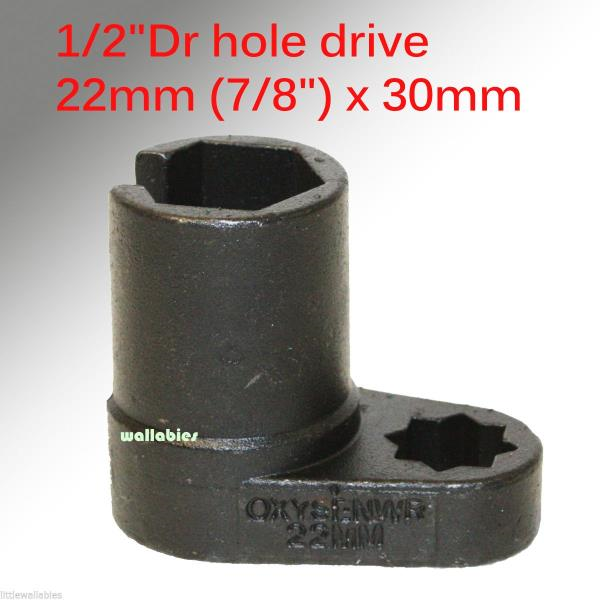
Torqueing the strut bearing hat top nut onto the strut is one of those things you don't really think about until you have to do it. Essentially, the issue here is that the strut shaft will spin if you try to just tighten the 22mm-7/8in strut nut alone. This means you have to use some way to counter hold the strut shaft. The factory Sachs struts have a hex head keyway, on Koni's that space is occupied by the adjusting tab and instead you have a 11mm nut. Of course all of these counter holding spots are blocked if you use a traditional socket and ratchet.

A lot of people suggest using a impact wrench here to spin it fast enough and that often works (and is a great method for removal).  However, there is very little chance of getting the nut close to 55 ft/lb and instead it will likely be way over tightened. On the flip side, others suggest a strap wrench but it is unlikely it can counter hold the necessary torque on the slippery strut shaft.

The solution I devised was to use a offset deep oxygen sensor socket. Make sure you get a deep well that is at least 25mm long as it needs to go down decently far if you are using the factory style strut bearing hats. These are available from eBay and other places for ~$10 or less. With this socket I could use a torque wrench while at the same time having a 11mm deep socket on the Koni strut nut.

Hopefully this helps some people out who have encountered this issue.

Wednesday, July 25, 2018

Turbo Auxiliary Coolant Temperature Sensor Pipe Modification - Part 2

In my previous post on this subject I outlined how to fabricate/modify the coolant pipe and fittings for the GT series turbo. In this post I'm going to discuss plumbing it into the cooling system.

For the coolant "Y-pipe" we have to make two connections. The longer arm passes under the intake manifold throttle body to intercooler pipe coupler and connects to the middle of the coolant reservoir about 6 inches away on a fairly straight path. The tricky part here is the input on the reservoir is considerably larger then the Y pipe. The Y pipe can use a 5/16 ID hose while the reservoir needs 3/4. Thankfully there are some Chevy and other applications that use a preformed straight 3/4 to 5/16 hose of 6 inches or longer. I was able to get one for less then $10 at the local Advance Auto. Then all the remained was to cut down the reducer hose to the appropriate length

The short arm connects to the coolant crossover pipe at the front of the engine bay. Both ends of this connection are the same size; I used 5/16 straight heater hose to make this connection.

Some additional notes regarding clearance with intake manifold, intercooler pipe and coolant "Y-pipe". The fit of all of the components in this area is very tight, even slight changes in the type of clamp, clamp position, thickness of silicone couplers, brand of fitting used in Part 1 of creating the pipe and other factors play a significant role in having enough space for everything to fit. In the worst case scenarios you won't have enough space, propping up the throttle body side of the intake manifold and the inside edge of the intake manifold will not sit flush with the cylinder head. The gap here can often be difficult to see; you can get a decent idea by shining a bright flashlight into the fuel injector port of the intake manifold in a dark garage and see if any light leaks out the inside gap. Make sure to cover or install a spark plug to block that source of light.

If during the test fitting you have additional clearance between the hood and the highest point of the intake manifold I would recommend either using a 1/8" phenolic intake manifold spacer or 2 factory gaskets on each runner. This will give you a bit more height to clear your plumbing and will make subsequent removals/re-installations a lot less finicky.  

For the turbo auxiliary coolant pump side all that is required is to cut a small amount off the factory 90* hose to make the slightly tighter bend to the new 10 push loc barb.


Thursday, July 19, 2018

DIY Oil Line Fitting Shopping List

If you are planning on building your own oil cooler lines you'll need a couple of adapters to make it happen. The AN to metric adapters are definitely a bit expensive at around $20 each. Below is the short list of items required:

2x -12AN 45 Degree hose end
2x -12AN 90 Degree hose end
4x -12AN male to M22x1.5 male
1.5M -12AN hose

Monday, July 16, 2018

Tial Wastegate Vacuum Hookup and Orentation

I made a quick graphic to show the correct way to setup vacuum hoses for Tial brand wastegates with a manual boost controller. Since the Tial valves work in reverse of the stock/Lindsey units the vacuum port orientation it reversed.


Figure of Tial 38mm installed in car. Borrowed from Rennlist

Sunday, January 28, 2018

Intense Wheel Restoration (Ammo NYC method)

Not long ago, I picked up a set of BBS Carrera 3 wheels for a really nice price on the second hand market. As with the majority of used wheels they had there share of imperfections this included some mild curb rash, black buildup (brake dust, dirt, asphalt) on most of the rim interior and scratches from improper cleaning maintenance on the front faces. I figured I would try my best to bring them back to life and if I was still unhappy I would consider sending them out for professional repair and repaint.

I mainly followed Larry's procedure from Ammo NYC on how to go about cleaning them. Larrys video here. The only major difference for my method was that since I do not own a RA polisher I had to do all the compounding by hand. I took some photos along the way to document how it came out.

Cleaning Materials (Wheel Cleaner, Dish Soap, Spray Wax, 105 Compound, Ultimate Compound, Sponge, Soft Brush, Clay, Microfiber Towels)
In addition to the cleaning materials pictured above I also used a respirator (during compounding), nitrile gloves, old towels and a large plastic storage bucket.

Pictured below is the initial condition of the rim, I don't think the camera was able to pick up the fine scratches that resulted from poor cleaning technique but trust me they were there on the majority of the outer lip and between the spokes.

Initial Condition - Front

Initial Condition - Back
Since it is winter and cold here in the northeast I attempted to do everything in my bathroom. And aside from having the sit on the floor while doing the manual labor that location worked pretty well.


Wheel in dish soap bath

Resulting water after dish soap/wheel cleaner bath and sponge cleaning


Rim after dish soap bath

Rim after clay bar treatment. Some of the black stain was removed and the clay was good at removing stuck asphalt

Rim after compounding. 105 worked well by hand.

Final Result
After I was finished with the compounding I did do one additional step which was to use Klasse All-In-One to add a layer of protection back on the surface to help prevent/reduce future build up. I did not take a photo after that. Total time per wheel for all 4 steps was about 6 hours, with a large portion of that being devoted to hand compounding.

Tuesday, August 2, 2016

Turbo Auxiliary Coolant Temperature Sensor Pipe Modification

One of the accommodations needed to be made when outfitting a new turbo that does not use a KKK center section is to re-route the coolant temperature sensor for the auxiliary coolant pump. The sensor triggers the coolant pump to turn on and off after the car has been shut down to continue to flow through the turbo to reduce wear. It can cycle many times after the car is turned off to accomplish its job. Basically this functions as a OEM turbo timer.

The turbo I have replaced the K26 with is a Garrett GT3076R. The GT30 uses a 14mm x 1.5 fitting on both sides of the center section for cooling. To adapt to a more common fitting size I used a 14mm male to -10AN male. -6AN and - 10AN are the most readily available center section adapters for the GT. I choose to go with the larger -10AN to ensure maximum flow. A 1/2" copper crush washer on the 14mm side that connects to the turbo is also necessary.

To modify the sensor pipe we first need to cut off the banjo fitting/pipe that is attached to the sensor mount (I borrowed the general idea for the modification from Paulyy on Rennlist). Using a hacksaw and a bench vise to hold the pipe you can make quick work of this. Depending on the cleanliness of the cut you may choose to smooth the surface with medium grit sandpaper. Next, I drilled the hole to the necessary size for a 3/8" x 18 NPT tap. Required drill sizes are either 37/64" or 9/16". Then tap the hole with the 3/8" tap. This will allow us to a 3/8" NPT to -10AN adapter fitting. Make sure to use thread sealant on the fittings. After cutting I painted the pipe with VHT engine metallic titanium silver blue.


The layout of the adapters is as follows. On the sensor side starting with the nearest to the turbo 14mm male to -10AN male > 90* swivel -10AN female to -10AN female > -10AN male to 3/8" NPT. On the auxiliary coolant pump side 14mm male to -10AN male > -10AN female to -10AN female coupler > -10AN male to 10 push loc hose barb.
 
Due to the very tight center section of the GT series turbo and the close proximity of the hot side clocking bolts the 90* swivel adapter is going to have to some problems fully tightening down on the 14mm adapter in most scenarios. One option to replace the 2 clocking bolts with low profile bolts (similar to what is used near the oil drain). Alternatively you can file down the points on the front 1/3 of the swivel adapter to gain enough clearance to pass the bolt; I ended up choosing the later. 


Thursday, July 28, 2016

Power Steering Hard Line Cooler Hose and Clamp Discussion

One of the power steering hoses off the reservoir on my car was in pretty poor shape. Of course it is the one with the cooler hardline integrated (since I replaced the other hose already). This part is expensive if you go for a OEM replacement because it comes with the cooler hardline coil and crimped hose as one unit. To add to the frustration the hardline end is a different diameter then the reservoir.
 
Thankfully Bruce at Arnworx has taken some of the annoyance out of this job by having a nicely preassembled hose with a protective heat shield over the 90* bend area where the hose meets the bending reducer. Available here. Installation is pretty straight forward so I'm not going to cover that but instead I'm going to talk about why the old hose was in such poor shape.
 
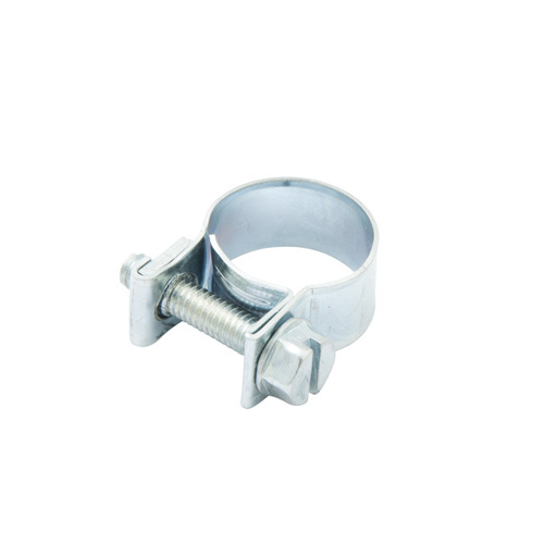
The main reason was a result of a low quality hose clamp. There are a wide variety of clamps on the market and in my experience the kind that was installed on this hose are the worst. They are the perforated worm clamp. Because of the punched out metal to make the screw track these leave large impressions on rubber hose. Silcone hose and couplers are even more susceptible to clamp damage then rubber so a quality clamp is essential when using Silcone. A better solution is either an embossed worm style clamp, fuel injector style, t-bolt or other clamp that has a solid continuous protective surface on the inside. Thankfully most of the factory clamps on the 944 are Norma brand embossed worm style so this is generally not an issue but worth thinking about if you are going to be replacing aging clamps.


Embossed Clamp
 
Worm Clamp
Fuel Injector Style Clamp
 

Friday, July 15, 2016

Fuel Tank Cover Strap Refurb

While replacing the fuel strainer at the lower part of the fuel tank I noticed that the support strap for the fuel tank lower cover was pretty rusty. In fact it looked like it spent a little too much time at the enchantment under the sea dance. I figured while I was down there I should probably refurbish the part.

Before
 
In addition to paint, the factory also installed some cushioning foam to the top of the strap where it contacts the covers and gas tank. Very similar resemblance to foam weather-stripping from home improvement stores. I was surprised to see on the Frost King packaging that it states: "Many automotive and marine uses". 
 
Step 1: Using a grinder or drill wire wheel as much rust, old paint..etc from the part as possible. I used a grinder with a 4" brass wire wheel. Ideally a media blaster is best for this type of work but I don't own one.
 
Step 2: Clean/Wash/Dry the part to prepare for painting. I cleaned it with simple green and a scrub brush, then rinsed with water. Brake cleaner is another popular choice.
 
Step 3.1: Paint the part. For this piece I am using 2 different paints. The first is a rust converting paint such as Rustoleum Rust Reformer. Even though I probably removed the majority of the rust during step 1 this goes the extra mile to be sure its not coming back. 2 light coats of Reformer about 10mins apart followed by a 24 hour drying cycle.
 
Note: If you are going to paint inside like I had to due to weather conditions make sure you have a vapor respirator mask. You can make a "booth" area out of some old cardboard and hang it from an A frame ladder, just be creative!
 
 I ended up using a bit more brown paper then pictured on the sides to catch overspray.
 
Step 3.2: Follow up with VHT Chassis satin black as the top coat. 2 light coats followed by 1 medium "wet" coat, allowing for 10mins drying between each application. The part should be ready to handle in 3 hours.
 
Step 4 (Optional): Apply Frost King adhesive weather-stripping to the section of the strap that contacts the gas tank and lower covers. If needed use 3M Super 77 for additional adhesive on weather stripping. Clamp for about an hour to assist the glue. Super 77 is pretty tacky, so you'll need rubbing alcohol for removing any extra.


Step 5: Bask in the glory of knowing no one will notice your hard work on this part hidden away under your vehicle.
 

Finished!


Monday, July 11, 2016

General Project Update

Project update as of early July 2016.
 
I'm waiting on the collar nut for the timing roller and a few other random parts. I also need to send some parts to the local plating shop to get a new yellow zinc chromate finish.
 
LR Stage 2 cylinder head after decking to remove o-ring grooves (Performed at Windsor Automotive Machine)
 
 
Cyl 1 @ TDC with the gasket on
 
If you look carefully you might be able to see the alignment marks I scribed on the balance shaft housing.
Extra help with alignment for a no cover install.


Saturday, July 9, 2016

Fuel Damper/Fuel Pressure Regulator and Jumper Hose (Fuel in Vacuum Lines)

The fuel damper and associated jumper hose have been a source of problems for these cars especially as they get older. The rubber hose is the most straight forward as it tends to get rock solid with age and eventually becomes a location for a fuel leak.
A failing fuel damper and/or fuel pressure regulator is a bit harder to identify. Symptoms consist of fuel in the vacuum line at the back of the damper/regulator which in severe cases can travel into the intake manifold or even the KLR vacuum line. Since the KLR line is clear you can actually spot the fuel traveling in the hose (See photo 2 below, the trapped gas is inside the circles). Others symptoms are hard to near impossible hot starts and fuel pressure loss over time at the rail causing long, lazy starts. In the case of the difficult hot starts this is likely due to the fact that as the gas migrates its way down the clear vacuum line and arrives at the KLR computer sensor it really confuses the system; when the gas eventually dries out near the computer things will appear to operate as normal for a brief period until the cycle repeats again.
Replacement on the bench if the rail has already been removed from the car can be a bit tricky since it can be a bit awkward to gently yet firmly clamp the rail to a work area to allow removal of the large nut securing the damper to the rail. Mine was particularly stuck and required me to use a chain whip vise grip on the damper to provide enough counter torque against a breaker bar.

Gas in KLR Vacuum Line (Image: 951North - Rennlist)

Friday, July 8, 2016

Flywheel Measurements and Pins

Switching to a aftermarket flywheel? Or perhaps you have acquired a flywheel with missing or removed "grub screws". I have taken a few measurements off the factory 87 flywheel which should assist in setting the screws to the correct height. This is important because the screw is what the factory sensor reads to determine engine position. If it is not set to the correct height you can get problems from erratic starting behavior to no starts. When setting the pins to the final height use some Loctite thread locker to ensure they stay at the desired height.
 
As a side note the stock flywheel has 3 screws, 2 on the same plane and 1 further back on a different plane. Most aftermarket wheels only have 1 screw. The stock Motronic engine managements uses a 132+1 setup. The 132 is the number of teeth on the ring gear mounted to the outside of the pressure plate, the 1 is the grub screw on the flywheel. So as it turns out 1 screw is all that is required as the other 2 are not used by the stock Motronic (I believe they were for a TDC sensor which was never implemented).


The SPEC scallop steel flywheel that will be replacing the stock wheel is pictured below. I set the pin tip to inside lip (a) to 119mm by adjusting the grub screw. Use some type of Loctite thread locker on the grub screw (I used the medium strength blue variety). The (b) measure was the same which it should be. The SPEC wheel overall has a slightly larger OD then the stock wheel, this results in the pin tip to outside lip measure being less than the stock wheel. If you had only taken the pin measure (c) from stock and set it for the new wheel the pin would have been 1.25mm too high.
 
 
To SPECs credit the new wheel comes with TDC markings already on it which is great. The upper mark where the factory OT and line would be is a little faint and I figured in a dark engine bay through the bell housing inspection port it might be difficult to see. I used a bit of pink nail polish to highlight the area.
 
Camera had a hard time picking up the engraved line for TDC mark but it is there.
 I also thought it would be worth mentioning here that SPEC flywheels made prior to May 2017 are the ones affected the increased diameter sizing issue. A secondary problem created by the increased size is in some cases it will create interference with the square wave signal the crankshaft flywheel sensor uses. Lindsey Racing has documented the issue here and offers a simple solution.

Thursday, July 7, 2016

Oil Pump Eccentric Tensioner Stud and Collar Nut

If you have switched model year engines at some point you'll know there were a lot of minor changes here and there which cause headaches at every turn. Since the 86' block uses the eccentric timing belt tensioner it requires a mounting stud and collar nut (#8 and #9 below) for the block. The stud part # 944 102 243 00 is generally difficult to find and is supposed to be no longer available. The specs for the stud are M10 x 1.5 thread x 101mm long. (On very early model cars it was 106mm long).


I was able to source some ASTM A193 Grade B7 (which is a bit better than 8.8) M10 x 1.5 yellow zinc chromate plated steel rod from McMaster Carr (#98942A116) which I will use to create the stud.
 
First step was to measure and mark with permanent marker the desired length of rod (I choose 106mm) as this gives a little extra wiggle room and you could easily fit 110mm without any clearance issues.
 
 
Next I grabbed a piece of scrap 2x4 and drilled the nearest standard size hole in the 2" side (I mostly only have standard size drill bits laying around). Then take a wood saw and cut a slot down the center of the 4" side. This will be where the hack saw will ride when the rod is mounted to our wooden jig. Place the rod into the jig noting your mark for length, looking for it in the center slot with a flash light. Now is a decent time to double check with a ruler or caliper the length to the center cut to ensure you got it right. Secure the rod with M10 nuts on each side.  
 
 
I then clamped the jig in a bench vise and used a jack stand to hold the extra rod up as this piece was 1m long. Using a hack saw cut through the center slot. Once completely cut you can use the nut which is already threaded on your new stud to help clean up the threads. Sandpaper or a file could also be helpful if the cut was not very clean.
 
 
Presto! A new 106mm stud without any damage to the threads from clamping.
 
 
As for the collar nut (aka flange nut, aka shoulder nut) Part # 944 102 243 00 it is 13mm overall height. This is not exactly a common size for a M10 x 1.5 flange nut. Solutions for this are to either stack a 3mm thick washer behind the more common M10 x 1.5 (10mm overall height) flange nut or to buy the part from Porsche, Pelican, Auto Atlanta..etc. As of 7/2016 the nut costs about $8
 
Special thanks to Van Svenson for measuring the stock collar nut.

ARP Cylinder Head Stud Kit

The stock cylinder head studs on these cars are one time use stretch design. They need to be replaced with either new factory stretch bolts or you can source reusable hardware from the aftermarket such as ARP or Raceware.
 
A quick note on removing the old studs. The factory used red Loctite to secure the studs to the block making them extremely difficult to remove. You may have success with double nutting the stud to remove it. If not the only other option is to weld a nut directly to the stud.


Installation is fairly straight forward but the most critical step is to ensure that the holes and threads in the block are clean. I used a variety of cleaning methods including (Shopvac with a long tube attached) while using compressed air with a long straw attached to dislodge and collect any large debris. Then I used brake cleaner, rotated the engine over on the stand so the deck surface was facing down and collecting all the cleaner with a paper towel. If the threads are slightly distorted you can chase them with a M12 x 1.5 cleaner/chasing tap (Which is different then a normal cutting tap). Alternatively if you have old head studs around you can make a cleaner by cutting a few v-grooves with a file into the threads.
 
The studs, nuts and washers should be installed with a coating of ARP ultra torque fastener lubricant. This stuff is great, its superior to anti-seize and gives accurate torque readings. Install the studs into the block hand tight only and test fit the head gasket and head for any unusual binding. Don't forget to reinstall the 2 alignment pins in the cylinder block if you had it surfaced. If everything checks out begin the 3 step torque process (Follow diagram below for sequence). 20ft/lbs then 50ft/lbs then 75ft/lbs. Best case letting the head settle for several hours between each stage.