Wednesday, August 29, 2018

Battery Tray


Couple photos of the battery tray area for a Pelican member to assist in a repair. The drain hole is circled in pink in the first photo, it is hidden slightly under the straight metal and leads toward the passenger wheel well.

Saturday, August 18, 2018

Torqueing Strut Bearing Hat Top Nuts

Torqueing the strut bearing hat top nut onto the strut is one of those things you don't really think about until you have to do it. Essentially, the issue here is that the strut shaft will spin if you try to just tighten the 22mm-7/8in strut nut alone. This means you have to use some way to counter hold the strut shaft. The factory Sachs struts have a hex head keyway, on Koni's that space is occupied by the adjusting tab and instead you have a 11mm nut. Of course all of these counter holding spots are blocked if you use a traditional socket and ratchet.

A lot of people suggest using a impact wrench here to spin it fast enough and that often works (and is a great method for removal).  However, there is very little chance of getting the nut close to 55 ft/lb and instead it will likely be way over tightened. On the flip side, others suggest a strap wrench but it is unlikely it can counter hold the necessary torque on the slippery strut shaft.

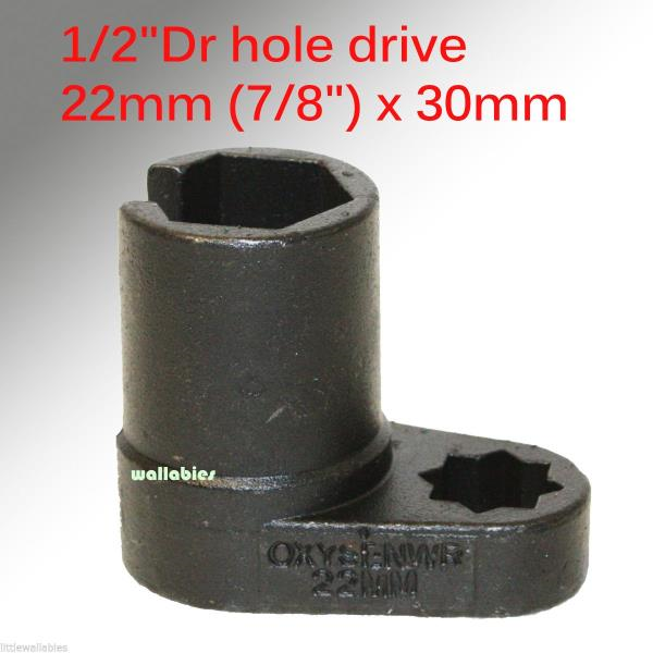
The solution I devised was to use a offset deep oxygen sensor socket. Make sure you get a deep well that is at least 25mm long as it needs to go down decently far if you are using the factory style strut bearing hats. These are available from eBay and other places for ~$10 or less. With this socket I could use a torque wrench while at the same time having a 11mm deep socket on the Koni strut nut.

Hopefully this helps some people out who have encountered this issue.

Wednesday, July 25, 2018

Turbo Auxiliary Coolant Temperature Sensor Pipe Modification - Part 2

In my previous post on this subject I outlined how to fabricate/modify the coolant pipe and fittings for the GT series turbo. In this post I'm going to discuss plumbing it into the cooling system.

For the coolant "Y-pipe" we have to make two connections. The longer arm passes under the intake manifold throttle body to intercooler pipe coupler and connects to the middle of the coolant reservoir about 6 inches away on a fairly straight path. The tricky part here is the input on the reservoir is considerably larger then the Y pipe. The Y pipe can use a 5/16 ID hose while the reservoir needs 3/4. Thankfully there are some Chevy and other applications that use a preformed straight 3/4 to 5/16 hose of 6 inches or longer. I was able to get one for less then $10 at the local Advance Auto. Then all the remained was to cut down the reducer hose to the appropriate length

The short arm connects to the coolant crossover pipe at the front of the engine bay. Both ends of this connection are the same size; I used 5/16 straight heater hose to make this connection.

Some additional notes regarding clearance with intake manifold, intercooler pipe and coolant "Y-pipe". The fit of all of the components in this area is very tight, even slight changes in the type of clamp, clamp position, thickness of silicone couplers, brand of fitting used in Part 1 of creating the pipe and other factors play a significant role in having enough space for everything to fit. In the worst case scenarios you won't have enough space, propping up the throttle body side of the intake manifold and the inside edge of the intake manifold will not sit flush with the cylinder head. The gap here can often be difficult to see; you can get a decent idea by shining a bright flashlight into the fuel injector port of the intake manifold in a dark garage and see if any light leaks out the inside gap. Make sure to cover or install a spark plug to block that source of light.

If during the test fitting you have additional clearance between the hood and the highest point of the intake manifold I would recommend either using a 1/8" phenolic intake manifold spacer or 2 factory gaskets on each runner. This will give you a bit more height to clear your plumbing and will make subsequent removals/re-installations a lot less finicky.  

For the turbo auxiliary coolant pump side all that is required is to cut a small amount off the factory 90* hose to make the slightly tighter bend to the new 10 push loc barb.


Thursday, July 19, 2018

DIY Oil Line Fitting Shopping List

If you are planning on building your own oil cooler lines you'll need a couple of adapters to make it happen. The AN to metric adapters are definitely a bit expensive at around $20 each. Below is the short list of items required:

2x -12AN 45 Degree hose end
2x -12AN 90 Degree hose end
4x -12AN male to M22x1.5 male
1.5M -12AN hose

Monday, July 16, 2018

Tial Wastegate Vacuum Hookup and Orentation

I made a quick graphic to show the correct way to setup vacuum hoses for Tial brand wastegates with a manual boost controller. Since the Tial valves work in reverse of the stock/Lindsey units the vacuum port orientation it reversed.


Figure of Tial 38mm installed in car. Borrowed from Rennlist

Sunday, January 28, 2018

Intense Wheel Restoration (Ammo NYC method)

Not long ago, I picked up a set of BBS Carrera 3 wheels for a really nice price on the second hand market. As with the majority of used wheels they had there share of imperfections this included some mild curb rash, black buildup (brake dust, dirt, asphalt) on most of the rim interior and scratches from improper cleaning maintenance on the front faces. I figured I would try my best to bring them back to life and if I was still unhappy I would consider sending them out for professional repair and repaint.

I mainly followed Larry's procedure from Ammo NYC on how to go about cleaning them. Larrys video here. The only major difference for my method was that since I do not own a RA polisher I had to do all the compounding by hand. I took some photos along the way to document how it came out.

Cleaning Materials (Wheel Cleaner, Dish Soap, Spray Wax, 105 Compound, Ultimate Compound, Sponge, Soft Brush, Clay, Microfiber Towels)
In addition to the cleaning materials pictured above I also used a respirator (during compounding), nitrile gloves, old towels and a large plastic storage bucket.

Pictured below is the initial condition of the rim, I don't think the camera was able to pick up the fine scratches that resulted from poor cleaning technique but trust me they were there on the majority of the outer lip and between the spokes.

Initial Condition - Front

Initial Condition - Back
Since it is winter and cold here in the northeast I attempted to do everything in my bathroom. And aside from having the sit on the floor while doing the manual labor that location worked pretty well.


Wheel in dish soap bath

Resulting water after dish soap/wheel cleaner bath and sponge cleaning


Rim after dish soap bath

Rim after clay bar treatment. Some of the black stain was removed and the clay was good at removing stuck asphalt

Rim after compounding. 105 worked well by hand.

Final Result
After I was finished with the compounding I did do one additional step which was to use Klasse All-In-One to add a layer of protection back on the surface to help prevent/reduce future build up. I did not take a photo after that. Total time per wheel for all 4 steps was about 6 hours, with a large portion of that being devoted to hand compounding.

Tuesday, August 2, 2016

Turbo Auxiliary Coolant Temperature Sensor Pipe Modification

One of the accommodations needed to be made when outfitting a new turbo that does not use a KKK center section is to re-route the coolant temperature sensor for the auxiliary coolant pump. The sensor triggers the coolant pump to turn on and off after the car has been shut down to continue to flow through the turbo to reduce wear. It can cycle many times after the car is turned off to accomplish its job. Basically this functions as a OEM turbo timer.

The turbo I have replaced the K26 with is a Garrett GT3076R. The GT30 uses a 14mm x 1.5 fitting on both sides of the center section for cooling. To adapt to a more common fitting size I used a 14mm male to -10AN male. -6AN and - 10AN are the most readily available center section adapters for the GT. I choose to go with the larger -10AN to ensure maximum flow. A 1/2" copper crush washer on the 14mm side that connects to the turbo is also necessary.

To modify the sensor pipe we first need to cut off the banjo fitting/pipe that is attached to the sensor mount (I borrowed the general idea for the modification from Paulyy on Rennlist). Using a hacksaw and a bench vise to hold the pipe you can make quick work of this. Depending on the cleanliness of the cut you may choose to smooth the surface with medium grit sandpaper. Next, I drilled the hole to the necessary size for a 3/8" x 18 NPT tap. Required drill sizes are either 37/64" or 9/16". Then tap the hole with the 3/8" tap. This will allow us to a 3/8" NPT to -10AN adapter fitting. Make sure to use thread sealant on the fittings. After cutting I painted the pipe with VHT engine metallic titanium silver blue.


The layout of the adapters is as follows. On the sensor side starting with the nearest to the turbo 14mm male to -10AN male > 90* swivel -10AN female to -10AN female > -10AN male to 3/8" NPT. On the auxiliary coolant pump side 14mm male to -10AN male > -10AN female to -10AN female coupler > -10AN male to 10 push loc hose barb.
 
Due to the very tight center section of the GT series turbo and the close proximity of the hot side clocking bolts the 90* swivel adapter is going to have to some problems fully tightening down on the 14mm adapter in most scenarios. One option to replace the 2 clocking bolts with low profile bolts (similar to what is used near the oil drain). Alternatively you can file down the points on the front 1/3 of the swivel adapter to gain enough clearance to pass the bolt; I ended up choosing the later.